Form Follows Force
Year: 2025
Free-form shell structures combine distinctive architectural expression with excellent structural performance and low-carbon benefits. Despite these advantages, they have not been widely adopted compared to other structural systems. The main challenges lie in their complex curvature, thin cross-sections, and sensitivity to defects, all of which require extremely high construction precision. As a result, traditional construction methods often prove complicated, costly, and difficult to execute.
This project explores parametric design methods for shell structures and investigates the use of prefabrication techniques for their construction. The target shell is based on a square plan with 1-meter side lengths. The realization of this prototype demonstrates the practicality of the proposed methods and highlights their potential for further research.
DIGITAL DESIGN OF SHELL PROTOTYPE
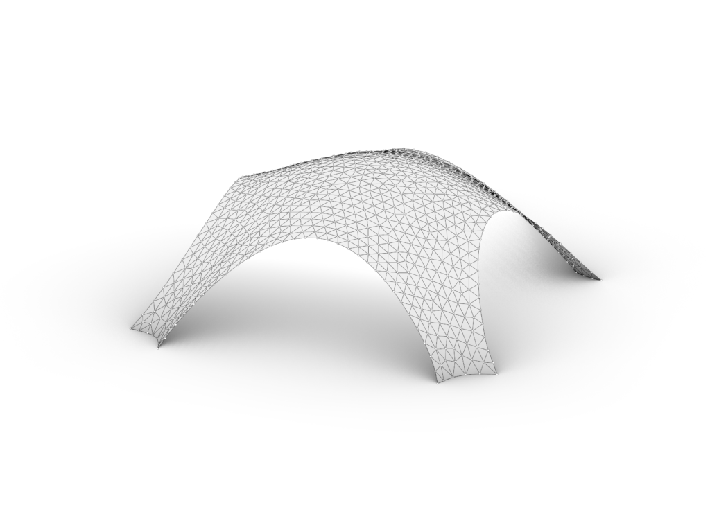
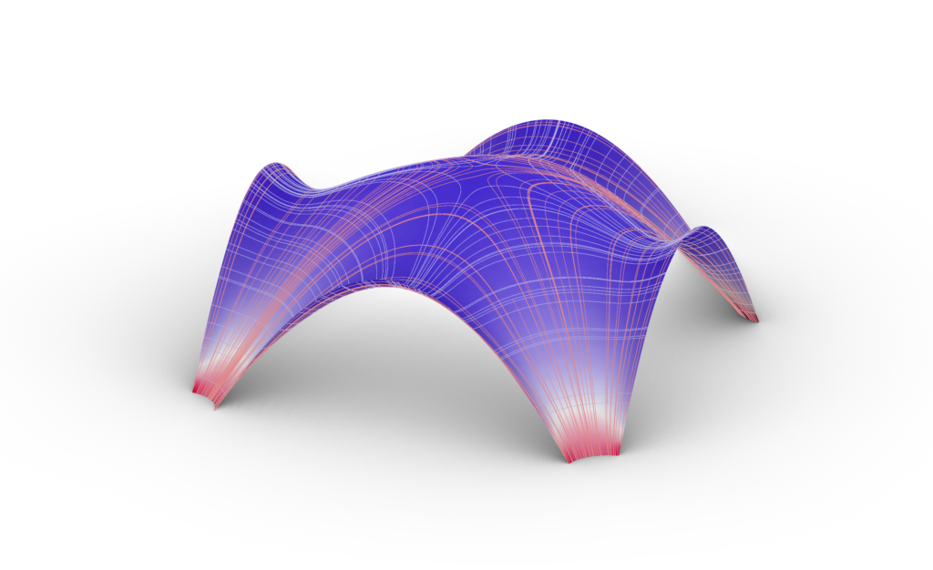
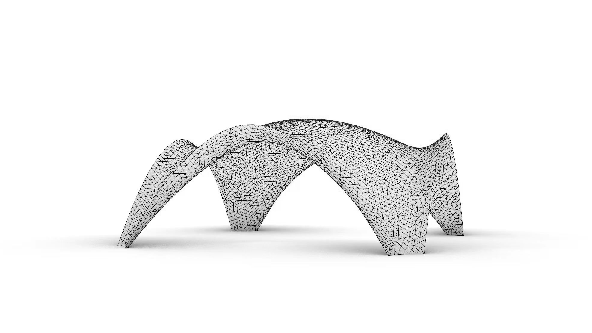
Use Kangaroo Physics to simulate the inverted hanging model and obtain the shell’s compression-only form.
Patching new edge curves and original mesh points to form the new shell surface.
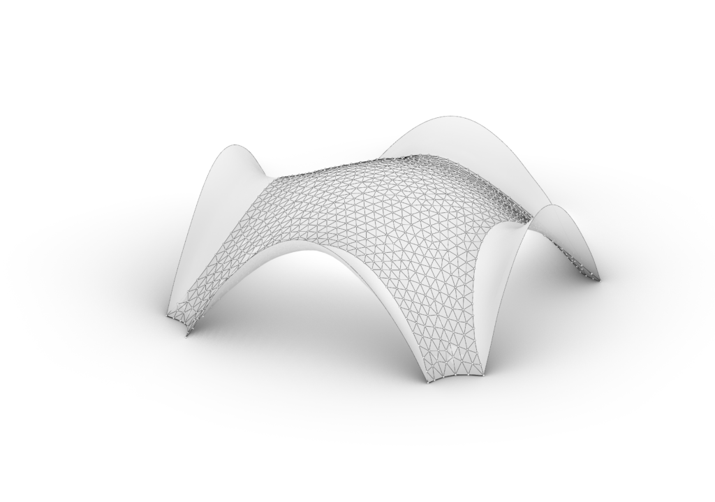
The shell geometry is slightly adjusted through a second hanging–inversion operation to regain a pure-compression geometry.
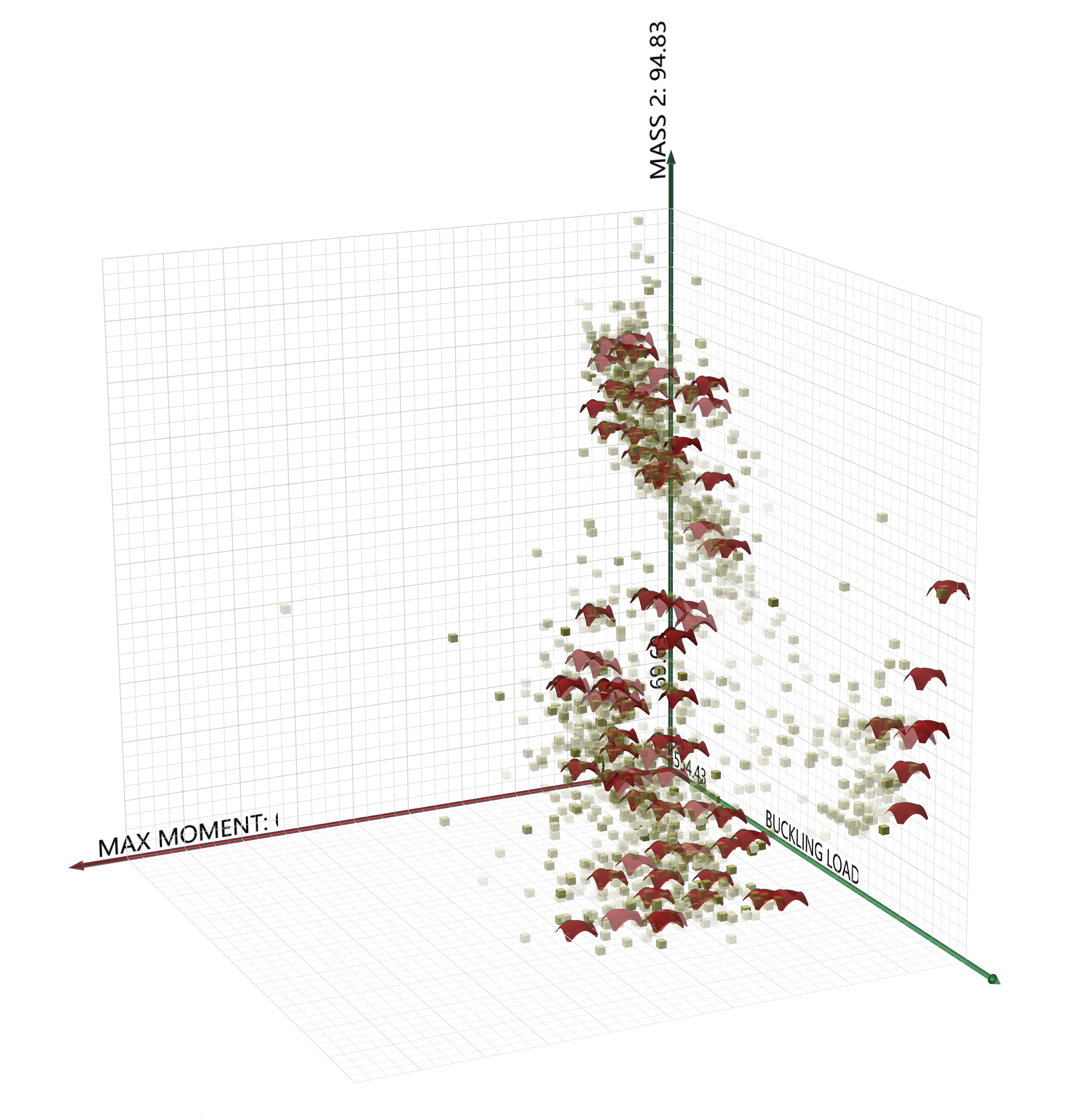
Select an ideal shell from the optimized solutions that achieves a balance between aesthetic quality and structural performance.
PREFABRICATION OF SHELL PROTOTYPE
PARTITION THE SHELL SURFACE
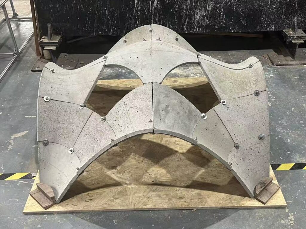
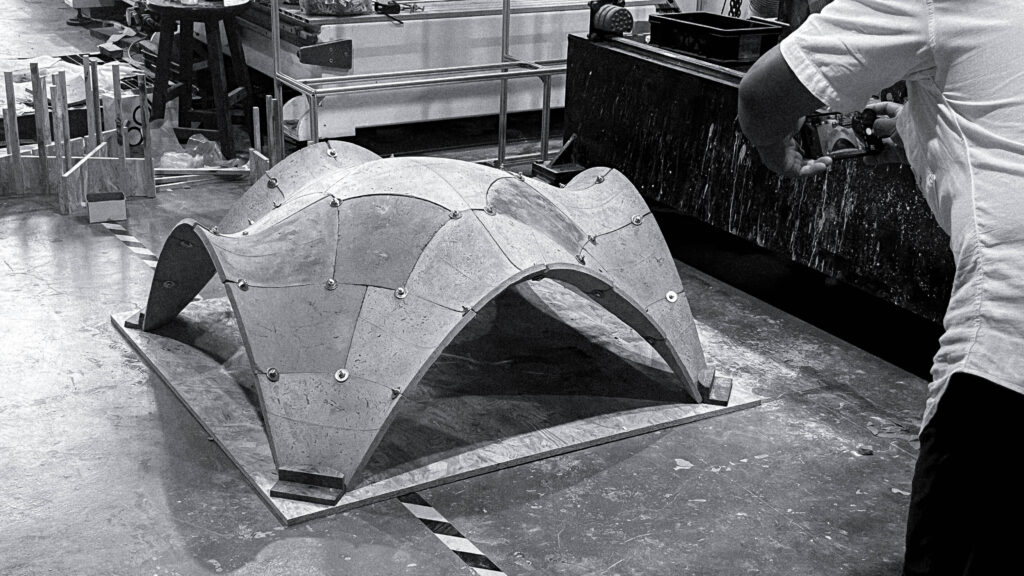
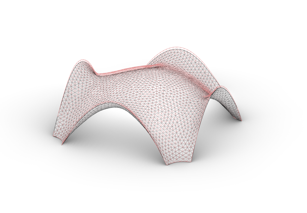
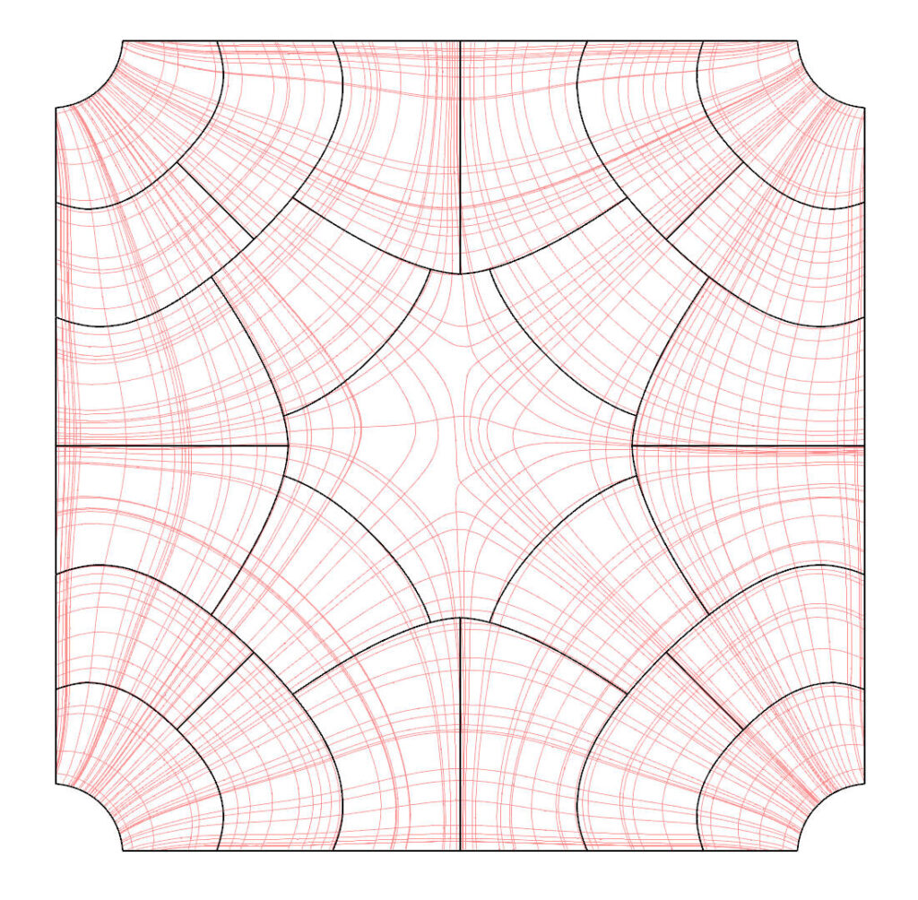
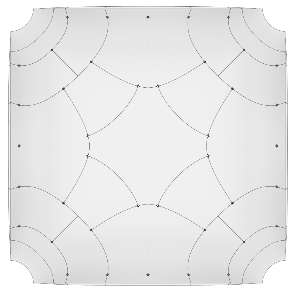
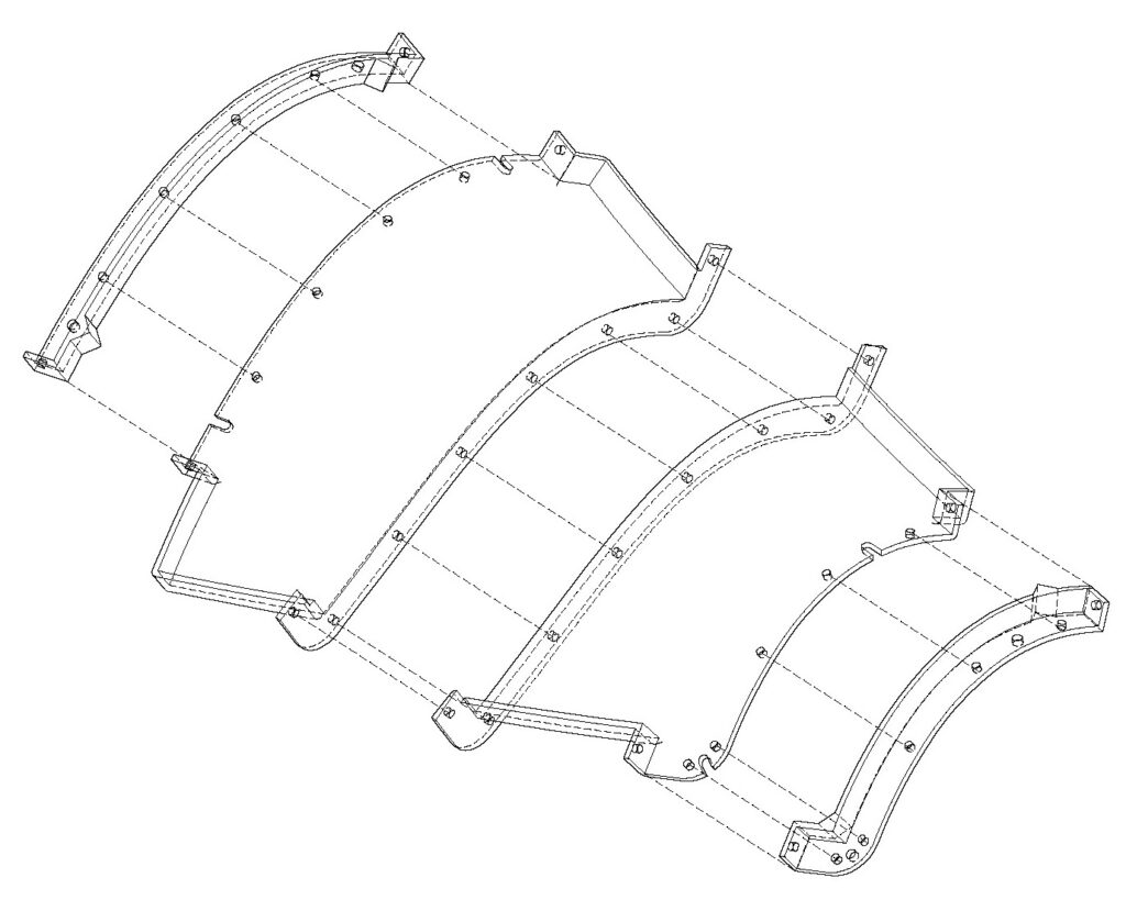
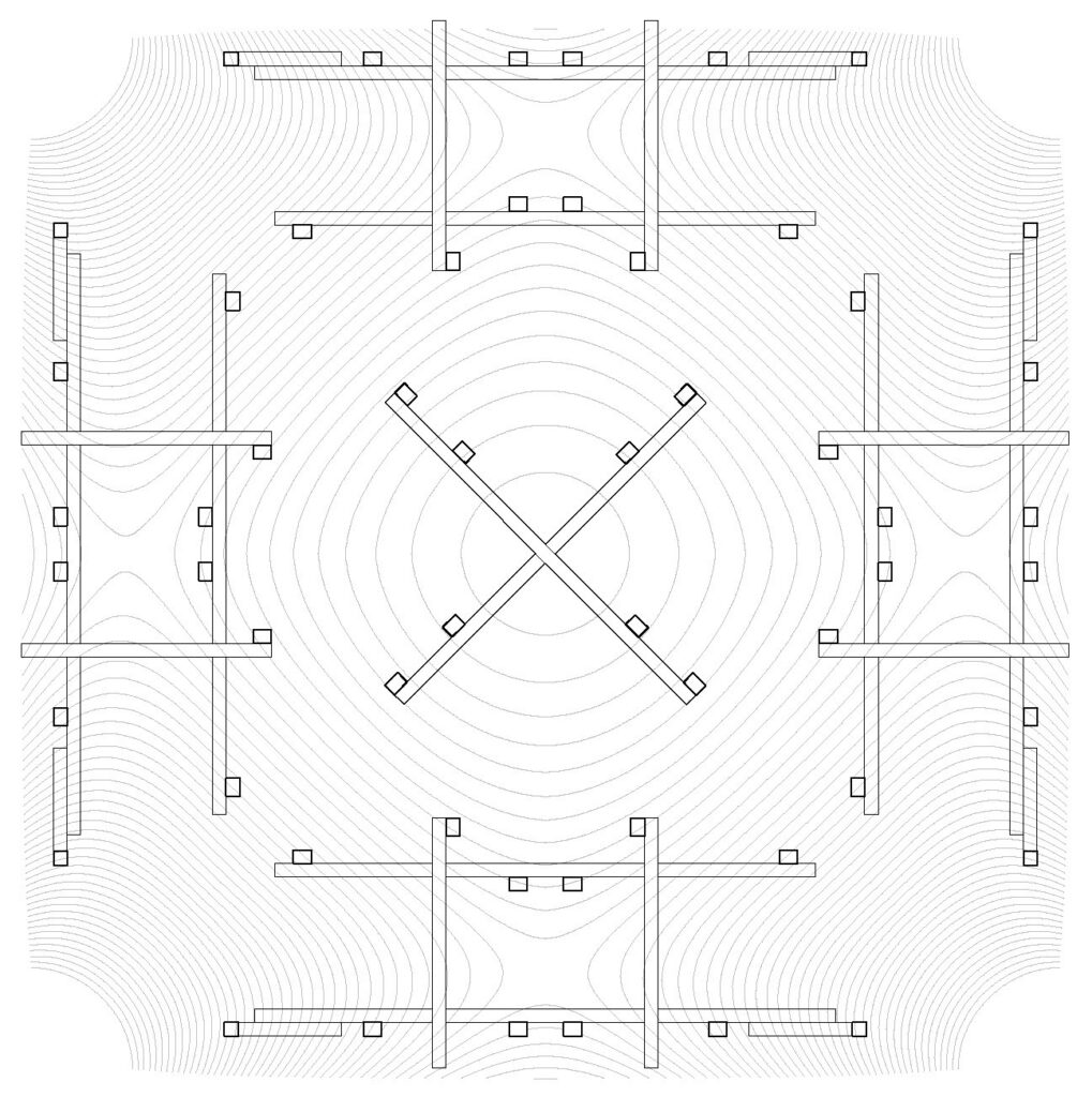
Prefabricated construction involves dividing a structure into components that are manufactured separately and assembled on site. For shell structures, its prefabrication requires developing an effective surface partitioning strategy as the first step. In this experiment, the partition lines are designed to be parallel or perpendicular to the principal stress trajectories, ensuring efficient load transfer between components and maintaining the shell’s structural integrity.
holes for bolts and washers
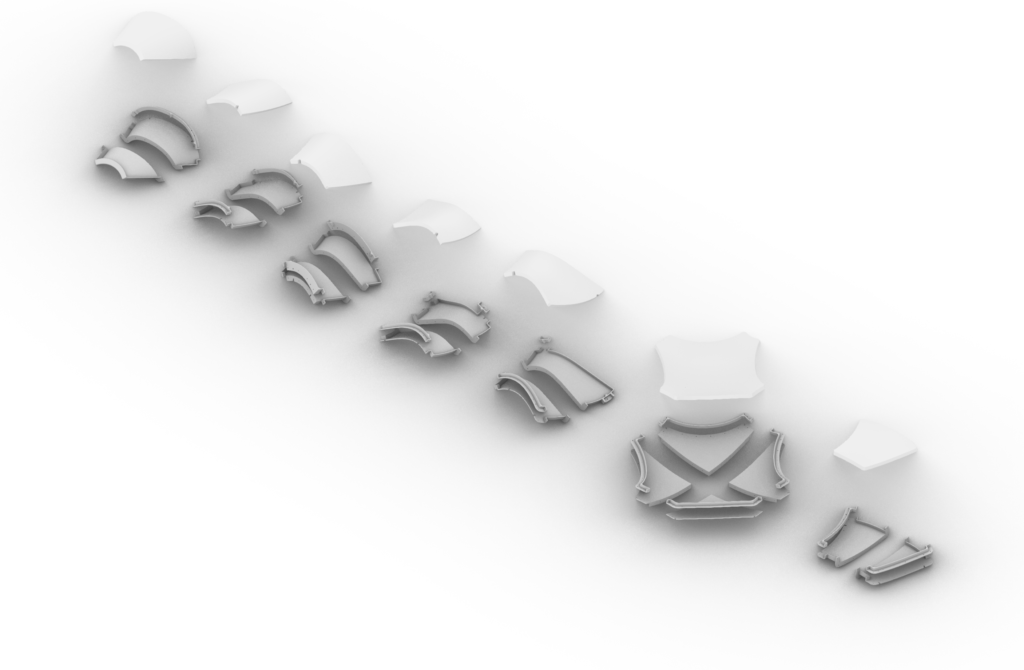
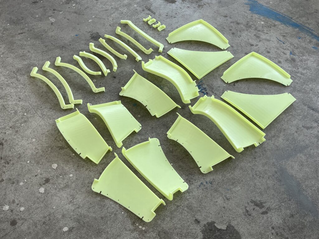
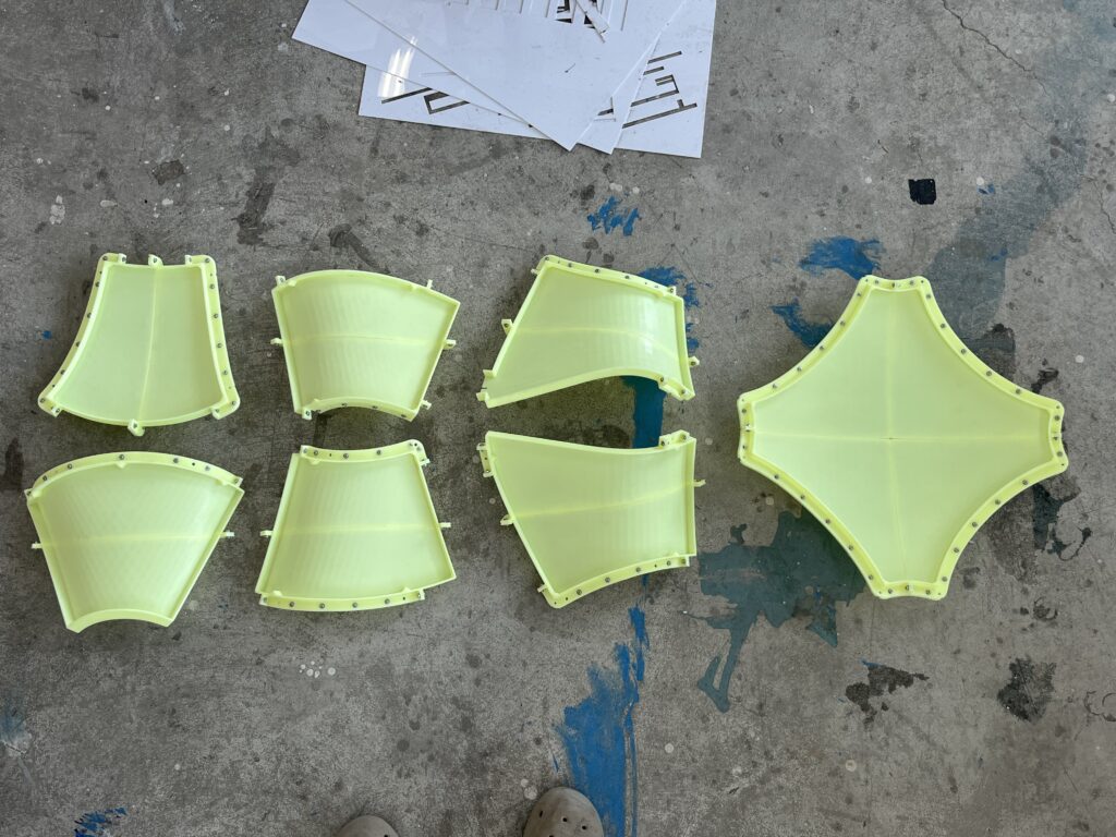
MOLD DESIGN
To ensure high surface accuracy, the formwork was 3D printed using high-toughness photosensitive resin. Its design focused on three main aspects: #1) Rigidity: Large, fragile panels were divided into smaller interlocking pieces to increase stiffness; #2) Assembly: Holes were placed at shared edges or points, allowing bolts with large washers to prevent movement; #3) Demolding: The formwork was split so each part could be removed easily. Separate edge pieces can be easily removed.
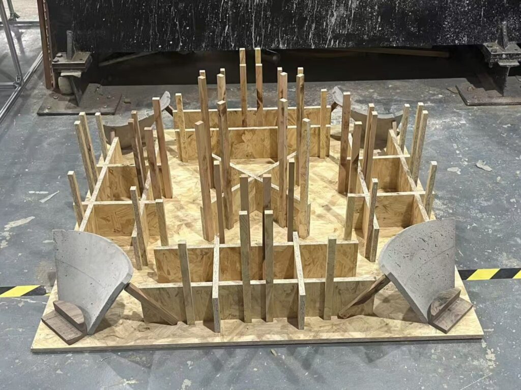
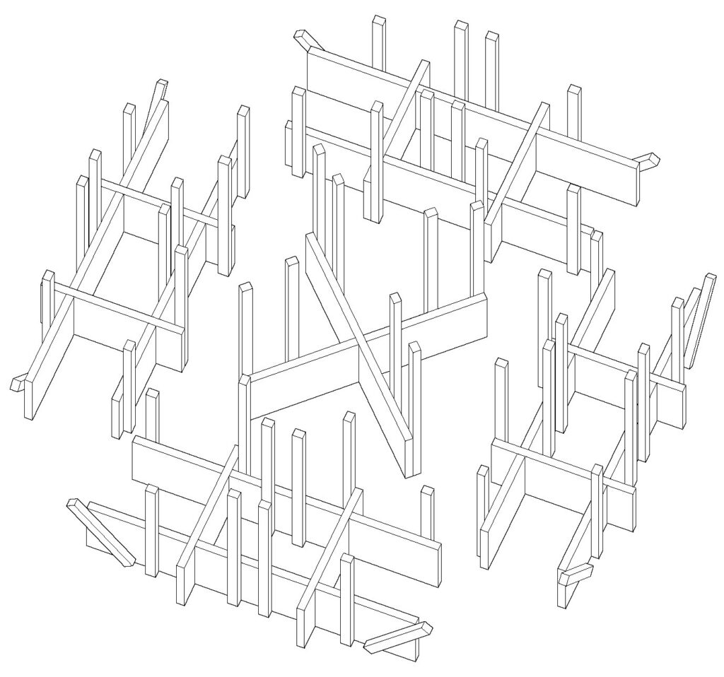
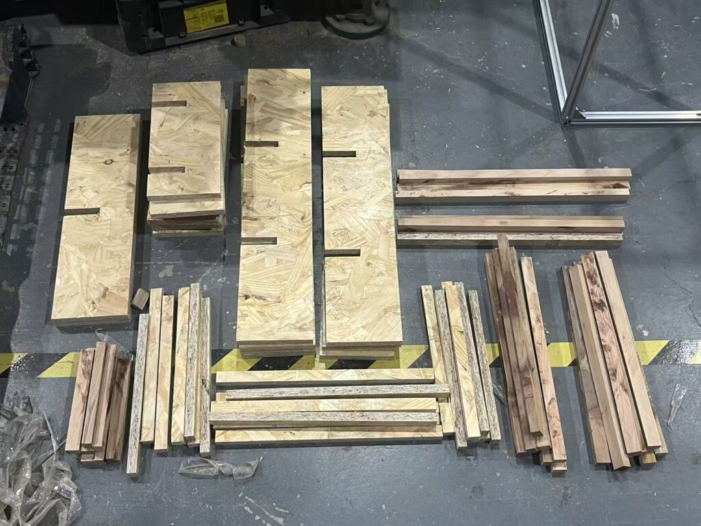
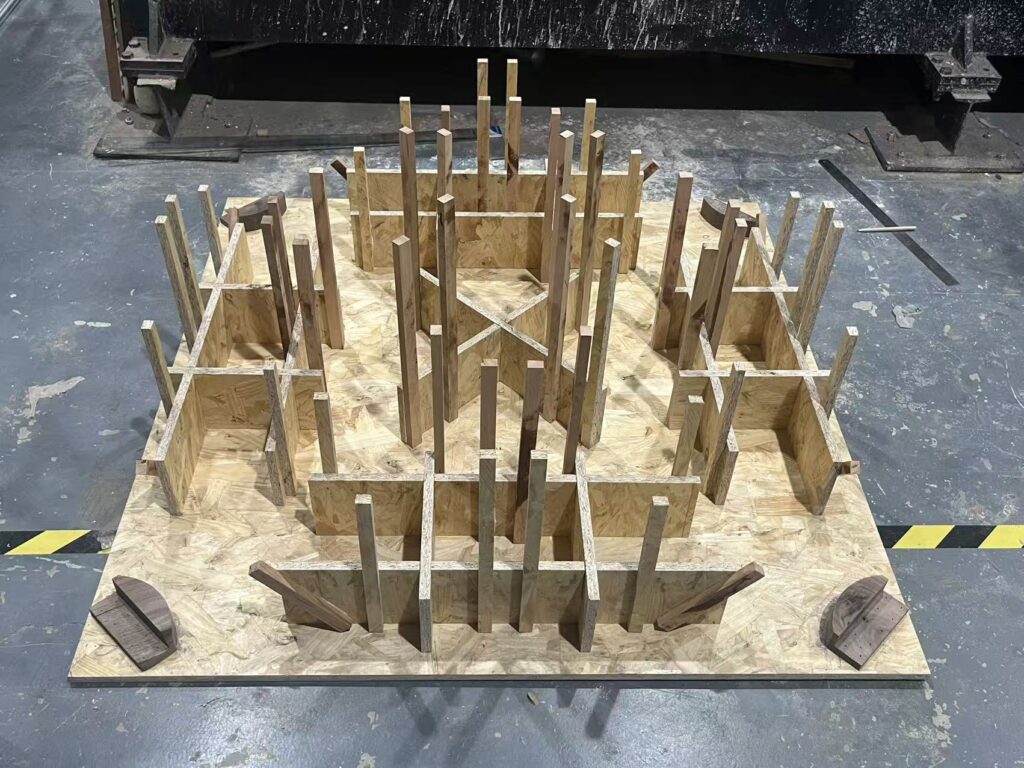
FALSEWORK DESIGN AND MANUFACTURE
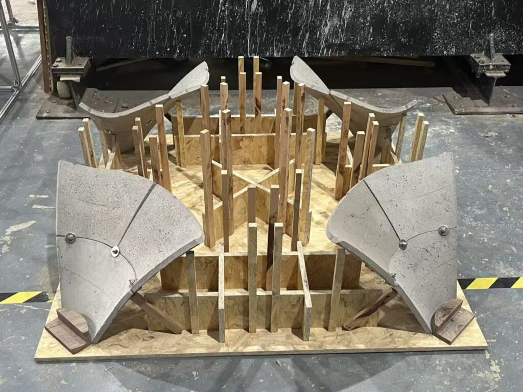
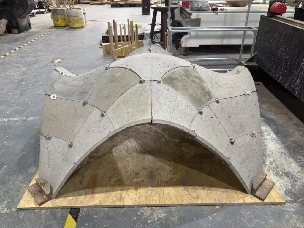
If all components are placed in their designated positions, loads can be transferred purely through compression. However, before the shell’s load path is established, the components cannot resist bending as a whole, so reliable positioning and supporting frames are required during assembly. In this experiment, 1.5 cm thick OSB boards served as the base, and wooden blocks were shaped into supports to resist the shell’s horizontal thrust. Assembly started from all four supports at once to help the components quickly make contact and form a load-bearing path.
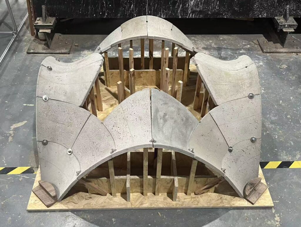
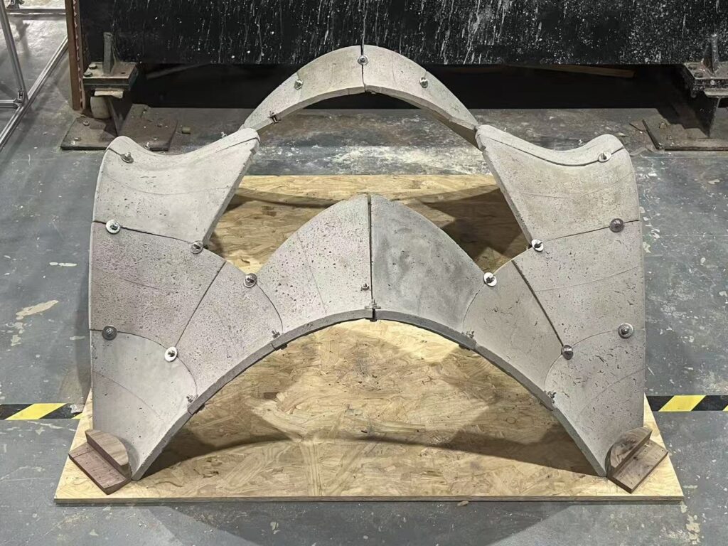
Due to machining and positioning errors, perfect edge alignment was not always achieved. In such cases, the angles and positions of components were adjusted before removing the supporting frames. Care was taken to prevent slippage or washer displacement and to keep the components mainly under compression rather than shear. After assembly, the supporting frames were removed.
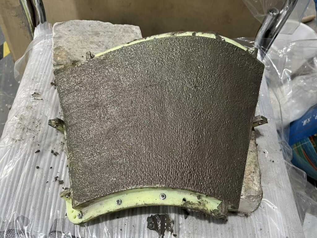
CASTING CEMENT MORTAR

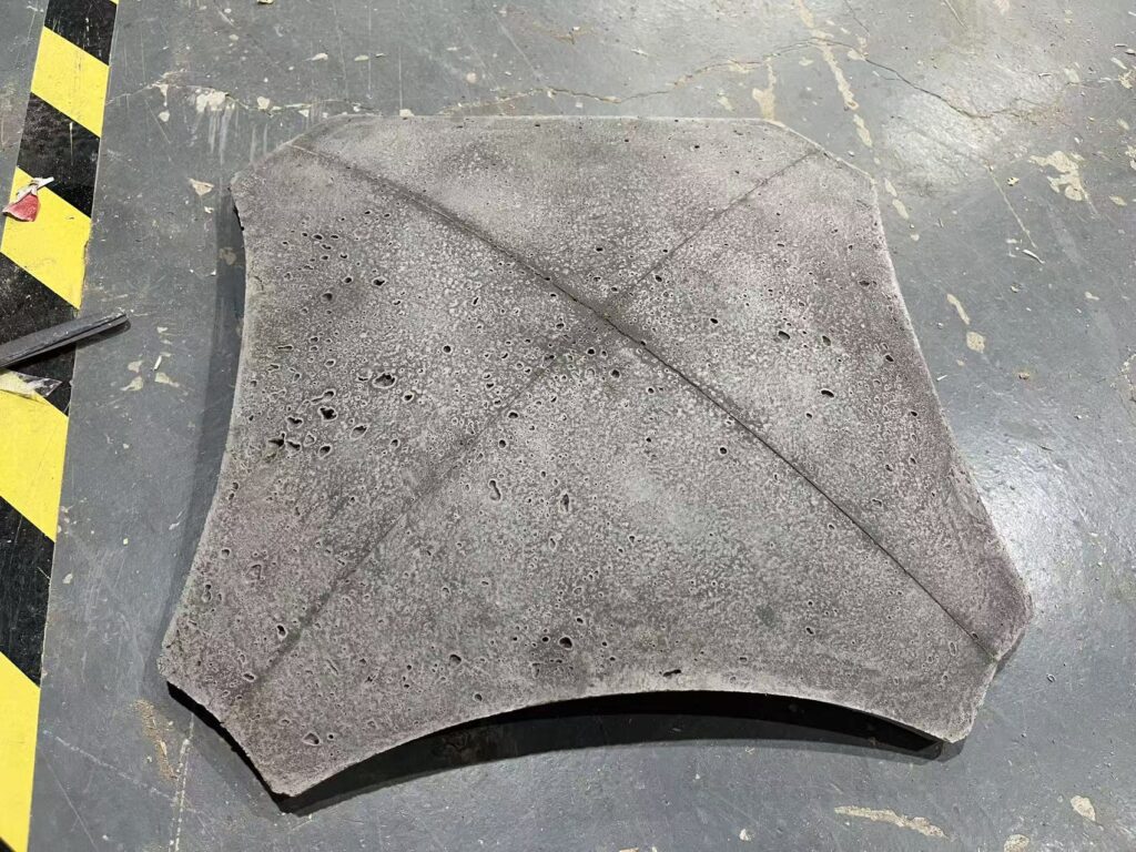
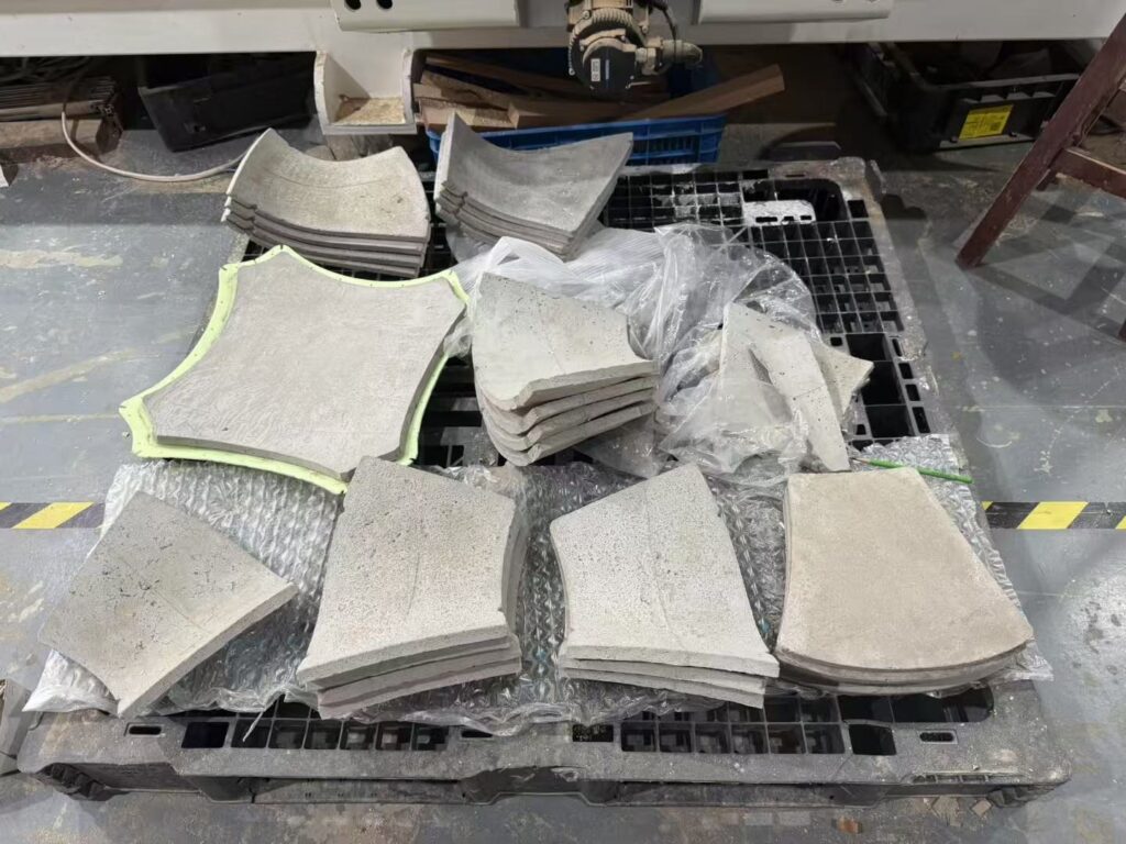
ASSEMBLY OF THE SHELL PROTOTYPE